| |
Construction |
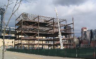
The construction of the North Shore Equitable Building, which lasted from October 1st, 2003 to December 31st 2004, was undertaken using a design build delivery method. Construction services were provided primarily by Continental Building Systems, the general contractor for the project. The total project cost came out to be roughly $70 million.
|
Electrical/Lighting
|
A 277/480 volt, 3 phase, 4 wire transformer on the garage level supplies power to the building. The electrical room is located on the first level and there is also an emergency generator on the garage level.
Most of the building’s lighting is provided by fluorescent direct/indirect pendants, wall mounted lamps and recessed wall washers. The direct/indirect lamps are 3500k, 32 watt, 277 volt T8 lamps and the wall washers are 3500k, 42 watt, 277 volt T4 lamps. Lighting on the parking level is provided by recessed metal halide lamps and the stairwells are lit with wall mounted fluorescent lights. The lighting for the entrance of the building is provided by 250 watt recessed metal halide down lights with quartz restrike. The first level lobby is lit with MR16 low voltage, adjustable recessed halogen lamps.
|
Mechanical
|
The mechanical system is a VAV system with 30,000 CFM air intake on the roof and 277 volt fan powered boxes on levels 2 through 5. This air intake meets the entire building load. Mechanical rooms can be found in the northeast corner of the garage level, above the lobby in the core of the building on levels 2 to 5, and on the roof.
The mechanical room in the garage level contains 2 of the building’s 4 boilers. There is also a boiler room in the southwest corner of the garage level with a 14” flue vent extending up through the exterior wall and out the roof.
The mechanical rooms in the core of the building contain the vertical water cooled self-contained unit. They also house the makeup air riser, exhaust air riser and relief air riser. A 400 CFM VAV box and a 1000 CFM fan powered box are between levels 1 and 2 above the lobby. A 26’ x 18’ open end relief duct connects to the return air plenum on levels 2 to 5. Intake and discharge louvers open to the east face of the building and are connected to the electrical room.
The mechanical room on the roof includes the air cooled chiller. 4” chilled water supply and chilled water return run from the chiller down through the shaft to level 1. The expansion tank, air separator and two pumps are housed on the roof as well.
|
Structural
|
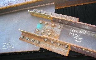
The structure of this building consists of a steel frame of beams and girders supported by steel wide flange columns and combined with both braced frames and moment frames surrounding the core of the building for lateral support. The steel framing on each level consists of 21 bays, typically 30’ x 42’ or 30’ x 44’. The floor system is a 5 ½” composite floor slab consisting of 3 ½” lightweight concrete over a 2” 18 gage composite galvanized metal floor deck reinforced with 6x6 W2.1xW2.1 welded wire fabric. The beams that support the floor system are typically W18x40’s in the exterior bays and W21x44’s in the interior bays and span in the longitudinal direction. These beams frame into girders which range in size from W24x62 to W30x116 and run in the transverse direction. Steel wide flange columns range in size from W14x311 on the first level to W14x48 extending up to the roof level.
The foundation consists of a 5 ½” reinforced slab on grade supported by concrete grade beams and a combination of 18” auger cast piles and steel H-piles. . The interior grade beams are typically 2’ wide and range from 2’ to 3’ deep whereas the exterior grade beams range from 3’4” to 4’ wide and from 2’ to 3’4” deep. The unique combination of the two types of foundations systems (auger cast piles and steel H piles) is designed to accommodate a future subgrade light rail transit line extension which passes directly below the building’s three eastern most bays.
The roof framing system consists of a 1 ½” 20 gage type B galvanized roof deck spanning longitudinally. The deck is supported by open-web K-series joists spanning perpendicular it. The joists are typically either 28” or 30” deep, span 42’ to 44’ and are spaced no further apart than 5’ typically. Girders are also used on the roof level and carry loads both from the joists framing into them and from the mechanical equipment housed on the upper roof level.
|
Plumbing
|
Various pipe types were used in the design, including schedule 40 pvc, SDR 35 pvc, copper drainage tubing, class 52 ductile iron and schedule 40 black steel. The domestic water riser is located near point C2 on the plan grid and the plumbing system connects to an existing 12” water main beyond the south face of the building. Domestic interior hot and cold water pipes, risers, branches and condensate drains are insulated with either P-1 or P-2 insulation. In addition to this, the plumbing equipment and associated items are designed to operate without reaching a sound or vibration level deemed to be objectionable by the architect.
|
Fire Protection
|
The fire protection services for this building were provided by Comunale Automatic Sprinklers Inc. Sprinklers are spaced one per 130 to 194 square feet, depending on the level. The majority of the piping length is 1 ¼” diameter piping with a smaller portion of the piping consisting of pipes at a 2-4” diameter. There are a total of 1568 sprinklers in the building with a 503.6 gpm allowance at 90 psi for the 1st level and a 250 gpm hose allowance on all other levels. |
Transportation
|
Circulation for the building is provided by four stairwells and three elevators which are located in the core of the building. Stairwell ST3 connects the first level and the garage level. Stairwells ST1, ST2 and ST4 all have access to levels 1 through 6 with stairwell ST1 extending up to the roof level mechanical room.
|
Audio Visual & Telecommunications
|
All audiovisual AC power requirements are supplied with surge protection. 110 volt AC power requirements are all provided on the same phase. Two wireless microphones and 6 ceiling speakers are installed in the first level lobby. Screen motors, screen control junction boxes, and video projectors can be found in all conference rooms. Ceiling mounted amplifiers and video projectors can be found in the second level training room and the third level gas control room as well as the dispatch room. Plasma display junction boxes and wall mounts for plasma displays have been designed into the second level crisis room and the trading room. Program speakers are installed in the second level training room, the fifth level training room and the gas control room. Two interface junction boxes, a screen control junction box, and a screen motor have been designed into the fifth level training room as well. There are also two LCD monitor junction boxes and two plasma display wall mounts in the sixth level waiting room adjacent to the board room.
|
|
|
|